
Performance Revolution in High-Frequency, High-Temperature, and High-Reliability Scenarios
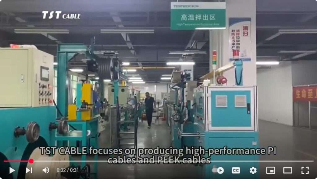
In modern radar systems (especially high-performance platforms such as airborne, shipborne, and missile-borne systems), high-frequency signal integrity and adaptability to extreme environments are the two core challenges for coaxial cables. While traditional PTFE (polytetrafluoroethylene) insulation possesses excellent dielectric properties, it suffers from fatal defects such as cold flow deformation, insufficient mechanical strength, and thermal expansion mismatch under high-temperature, high-power, and high-vibration conditions. TST CABLE PEEK (polyetheretherketone), with its unique three-in-one advantage of “high-frequency performance + mechanical strength + thermal stability,” is becoming a key material for high-end radar coaxial cables.
I. Core performance requirements of radar coaxial cables vs. TST cable PEEK matching degree
| Radar performance requirements | Pain points of traditional PTFE solutions | TST CABLE PEEK Solution | Performance improvement |
| Low dielectric loss (tanδ) | tanδ≈0.0002 (Excellent) | tanδ≈0.002 (@10 GHz) | Slightly inferior to PTFE, but still meets X/Ku band requirements. |
| Dielectric constant is stable (Dk) | Dk≈2.1 (extremely low and stable) | Dk≈3.2 (@10 GHz), excellent temperature/frequency stability | Phase stability increases (ΔDk<0.05 over -55~250℃) |
| High power capacity | Cold flow deformation → conductor eccentricity → breakdown | Compressive strength >100 MPa, dimensionally stable at high temperatures | Power capacity increased by 30% (at 250℃) |
| Wide temperature range operation | Softening and deformation at >200℃ | Stable operation at 250℃ | Operating temperature limit ↑50℃ |
| High mechanical strength | Tensile strength ≈ 25 MPa, easily scratched. | Tensile strength 90–100 MPa, excellent wear resistance | Vibration/bending life increased by 5 times |
| Low thermal expansion (CTE) | CTE≈100×10⁻⁶/℃ (much higher than copper) | CTE≈45×10⁻⁶/℃ (close to copper’s 17×10⁻⁶/℃) | Interface stress ↓60%, avoiding fretting noise. |
| Lightweight | Density 2.2 g/cm³ | Density 1.32 g/cm³ | 40% weight reduction (crucial for airborne/missile systems) |
PEEK does not surpass PTFE in all high-frequency parameters, but its overall reliability is irreplaceable in high-temperature, high-power, and high-dynamic radar scenarios.
“Sacrificing 0.1 dB/km insertion loss in exchange for a leap in system-level reliability” is a rational choice for high-end radars.
II. Typical Structural Applications of PEEK in Radar Coaxial Cables
2.1 Insulation Layer: Core Innovation Point
Overcoming technological challenges:
PEEK has a melting point of 343℃ and requires a dedicated high-temperature extruder (temperature control ±1℃).
Online laser diameter measurement + eccentricity meter ensures concentricity (Knowledge base: Zhongtian Technology achieves ±0.01mm control)
Performance advantages:
The dielectric strength remains >20 kV/mm at 250℃ (PTFE decreases to <10 kV/mm).
Phase stability: Phase shift <0.5°/m at -55~250℃ (PTFE phase shift >2°/m due to cold flow).
2.2 Sheath layer: Environmental protection
| Application scenarios | Sheath solution | value |
| Airborne radar | PEEK thin-walled sheath (0.3mm) | Lightweight and resistant to hydraulic oil corrosion |
| Shipborne radar | PEEK/TPU composite sheath | Salt spray resistance + flexibility balance |
| missile-borne radar | Carbon fiber reinforced PEEK sheath | Resistant to high-G impact (>50G) |
III. Typical Radar Application Scenarios and Value Validation
3.1 Airborne fire control radar (e.g., F-35 APG-81)
| need | Value of PEEK Cables | measured data |
| High temperature environment | Cables near the engine compartment need to withstand temperatures above 200°C. | Insertion loss change after aging at 250℃ for 1000 hours is <0.1 dB (X-band). |
| High vibration | Continuous vibration of 5–500 Hz during flight | Phase stability deviation after vibration testing <0.3° (>1.5° for PTFE scheme) |
| Weight loss needs | Every 1kg reduction improves the fighter jet’s maneuverability. | The weight of a single F-35 can be reduced by 8–12 kg (due to the replacement of all high-frequency cables on the aircraft). |
3.2 Shipborne phased array radar (such as SPY-6)
| need | Value of PEEK Cables | measured data |
| Salt spray corrosion | Marine environments require tolerance to NaCl/H₂S | The shielding effectiveness remains >100dB after 3000h salt spray test. |
| High power | GaN T/R module output power >100W | Power capacity increased to 150W (PTFE limit 100W). |
| Long-term reliability | Design life ≥ 30 years | Accelerated aging extrapolates lifespan to >35 years (Knowledge Base: Zhongtian Technology Deep-Sea Cable Verification Method) |
3.3 Missile/Missile Guiding Head
| need | Value of PEEK Cables | measured data |
| High G impact | At the moment of launch, the acceleration is greater than 50G. | No core breakage and intact insulation after impact test |
| Rapid Response | Startup time < 1 second | Signal transmission delay <1ns at low temperature (-55℃) |
| Space constraints | Miniaturized design (diameter <2mm) | Achieving 0.8mm ultra-fine coaxial cable (inner conductor 0.2mm) |
IV. Material Comparison of TST CABLE PEEK Cable vs. Traditional High-Frequency Cable
| Material | Dk (@10GHz) | tanδ (@10GHz) | Continuous operating temperature | Tensile strength (MPa) | Density (g/cm³) | Applicable radar scenarios |
| PEEK | 3.2 | 0.002 | 250℃ | 90–100 | 1.32 | High-temperature zones for airborne/shipborne/missile-borne systems |
| PTFE | 2.1 | 0.0002 | 260℃ | 20–25 | 2.2 | Ground radar/low temperature zone |
| FEP | 2.1 | 0.0008 | 200℃ | 23–28 | 2.15 | business communications |
| PI | 3.5 | 0.0025 | 260℃ | 70–100 | 1.42 | Satellite (vacuum environment) |
| PFA | 2.1 | 0.0003 | 260℃ | 25–30 | 2.12 | High-end ground equipment |
✅ PEEK Positioning:
Not the lowest loss, but the highest reliability.
It’s not the cheapest, but the one with the best total lifespan (maintenance-free, long lifespan).
V. Key Technical Parameters and Industry Standards
5.1 Core Electrical Performance (PEEK Coaxial Cable)
| parameter | Typical value | Test Standards | Radar requirements |
| Characteristic impedance | 50±1 Ω | IEC 62034 | 50 Ω system compatible |
| Insertion loss | ≤0.8 dB/m @10 GHz | MIL-STD-202 | X-band is acceptable. |
| Phase stability | ±0.5° @ -55~250℃ | IEEE 287 | Phased array radar is necessary |
| Shielding effectiveness | ≥100 dB @1–18 GHz | MIL-STD-461 | EMI protection meets standards |
| Power capacity | 150 W @250℃ (CW) | IEC 60169 | GaN radar support |
5.2 Aerospace Certification
MIL-DTL-17: General Specification for Military Coaxial Cables (High Temperature Clause Required)
AS22759: Aviation cable standard (PEEK requires additional testing at 250°C).
DO-160 Section 20: EMI Requirements for Airborne Equipment
NADCAP AC7101: Special Process (Extrusion/Termination) Certification
domestically produced PEEK cables :
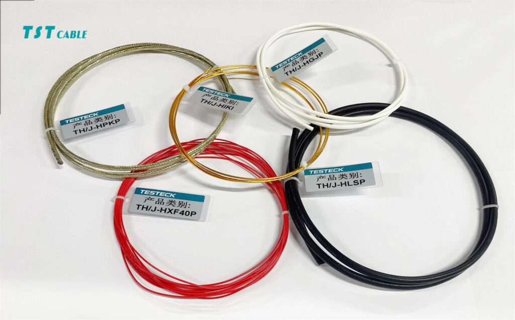
TST CABLE has developed a PEEK coaxial cable sample, which has passed the 200℃ environmental test and is undergoing airworthiness certification (driven by the demand for C919 components).
VI. Manufacturing Challenges and Solutions
| challenge | root cause | Solution | Industrialization Cases |
| Extrusion precision | PEEK has high melt viscosity. | Specialized screw design + online laser monitoring | Zhongtian Technology achieves a concentricity of >95% |
| Termination reliability | PEEK has high hardness, making it prone to damage during crimping. | Laser welding + PEEK dedicated connector | TE Connectivity patent scheme |
| Cost control | Resin is expensive ($600–800/kg). | Domestic resin alternatives (Zhongyan Co., Ltd. $400/kg) | Jiateng Electric reduces costs by 30% through bulk purchasing. |
| High-frequency consistency | Batch Dk fluctuation | Ultra-high purity PEEK (metal ions ≤1ppm) | Victrex APTIV™ HF Series |
VII. Future Technological Evolution Directions
Nano-modified PEEK:
Adding BN (boron nitride) nanosheets → Thermal conductivity increased to 1.8 W/m·K (heat dissipation optimization)
Adding graphene → tanδ decreases to 0.0015 (approaching PTFE levels)
Multilayer composite insulation:
PEEK (outer layer, mechanical protection) + microporous PTFE (inner layer, low Dk)
Balancing reliability and high-frequency performance (Rolls-Royce’s patent portfolio)
Intelligent cable integration:
PEEK matrix embedded FBG sensor → Real-time monitoring of cable temperature/strain
Data Direct Connection Radar Health Management System (PHM)
Additive manufacturing:
PEEK powder SLS printing of complex connectors → Reduces interfaces and improves phase consistency
VIII. Selection and Application Recommendations
8.1 When to Choose PEEK Coaxial Cables? Key Supplier Selection Considerations
✅ Material source: Victrex APTIV™ HF, Solvay KetaSpire® KT-880 HF (high frequency specific grade)
✅ Processing capabilities: ±0.01mm extrusion accuracy, 95%+ concentricity control
✅ Testing capabilities: Owns a 10 GHz vector network analyzer and a high/low temperature phase test bench.
✅ Fully Certified: MIL-DTL-17, AS22759, NADCAP
“In radar systems, insertion loss of 0.1 dB can be calibrated, but a battlefield loss of contact caused by a cable failure is irreversible.”
In the world of electromagnetic waves, stable transmission is a form of combat power.
Prioritizing reliability is an inevitable choice of our time .
The value of PEEK coaxial cables lies not in the “lowest loss” data measured in the laboratory, but in:
Non-softening at high temperatures—ensuring high power output for GaN radar
Non-deformation under vibration—maintaining beam accuracy for phased array radar
Non-corrosive in salt spray—ensuring 30-year service life for shipborne radar
Lightweight design—increasing the combat radius of fighter jets/missiles
With the advancement of three major trends—active electronically scanned arrays (AESA), GaN devices, and hypersonic platforms—
the comprehensive reliability requirements of radar cables have surpassed those of a single high-frequency indicator.
TST CABLE PEEK cables , with their pragmatic philosophy of “high-frequency sufficiency and all-around reliability,”
are becoming the new gold standard for high-end radar coaxial cables.
Action prompt:
Airborne/missile-borne projects: Prioritize evaluation of the PEEK solution (dual benefits of weight reduction and reliability).
Shipborne radar upgrade: Replacing PTFE with PEEK extends maintenance cycle to 10+ years.
Domestic production breakthrough: TST CABLE’s independently developed high-frequency PEEK cable boasts leading technology.
Also available in:
![]() English
English