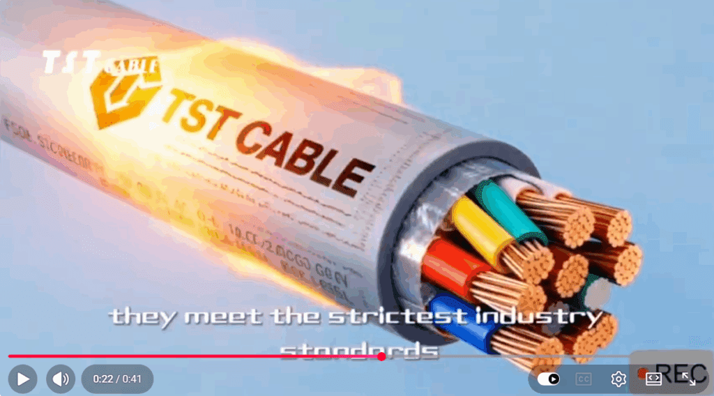

The high reliability of PEEK (polyetheretherketone) cables cannot rely solely on the superior performance of the material itself. It requires a comprehensive quality control system covering five key stages: material selection, structural design, precision manufacturing, rigorous testing, and standardized installation. The following are TST CABLE peek cable’s systematic reliability assurance strategies:
I. Source Control: Selecting genuine “aerospace-grade” PEEK resin
✅ Key measures:
Complete certifications: UL Yellow Card (RTI ≥ 250℃), NASA ASTM E595 Low Emission Report (TML < 0.5%, CVCM < 0.1%), and ECSS-Q-ST-70-08C or MIL-DTL-22759 Declaration of Conformity must be provided.
Ultra-high purity: Total metal ion content ≤ 1 ppm (ICP-MS detection), avoiding catalytic degradation or contamination of sensitive loads.
Batch consistency: Suppliers are required to provide DSC melting point curves (fluctuation ≤ ±1℃) and FTIR spectra for each batch to ensure molecular structure stability.
Risk avoidance: Beware of “industrial grade PEEK masquerading as aerospace grade” – industrial materials may contain recycled materials or additives, and the release of gases at high temperatures can lead to insulation failure.
II. Structural Design: Precise Engineering Matching Application Scenarios
✅ Core Principles:
| Application scenarios | Design Highlights |
| High-frequency signals (IMU/radar) | Ultra-high concentricity (>98%), Dk=3.2±0.05, shielding coverage ≥95%. |
| High-vibration environments (drones/robots) | Thin-walled + high-strength, conductor uses multi-strand fine wire (such as AWG30×7), minimum bending radius ≤5×D |
| Space radiation field (satellite) | Halogen-free, low hydrogen content, volume resistivity >10¹⁶ Ω·cm (protects against deep charging) |
| High-voltage system (800V electric drive) | Thick insulation layer (≥0.4mm), CTI > 600 V, corona resistance |
Tool support: Use electromagnetic simulation (such as CST) to optimize impedance matching, and use thermo-mechanical coupling analysis to verify thermal expansion matching.
III. Precision Manufacturing: Process is the “Last Mile” of Reliability
✅ Key process control points:
| Process | Control requirements | Detection methods |
| Extrusion molding | Temperature fluctuation ≤ ±1℃, constant speed | Infrared thermal imager + laser diameter gauge |
| Concentricity | ≥98% (High-frequency lines require ≥99%) | Online eccentricity meter (real-time feedback on X and Y axes) |
| Surface quality | Free from micropores, scratches, and impurities | High-magnification microscope + automated optical inspection (AOI) |
| Termination | Mechanical crimping is prohibited; laser welding is recommended. | X-ray inspection shows a weld void rate of <5%. |
Production line standards:
Cleanroom (Class 10,000 and above, protected against particulate contamination)
Full-process MES traceability (raw material batch number → finished product serial number)
IV. Rigorous Verification: Accelerated Testing Simulating Real-World Working Conditions
✅ Required Test Matrix (by Application):
| Test type | Aerospace/Military | Industrial/New Energy | Standard basis |
| thermal aging | 250℃×3000h | 200℃×5000h | UL 746B |
| Thermal vacuum cycle | -100℃↔+125℃×100 times | -65℃↔+150℃×50 times | ECSS-Q-ST-70-02 |
| Irradiation test | 100 krad (γ) | — | ASTM E1249 |
| Vibration fatigue | 10–2000 Hz, 15G, 10⁷ cycles | 5–500 Hz, 10G, 10⁶ cycles | MIL-STD-810H |
| Dielectric properties | Dk/tanδ full temperature range scan | room temperature test | IPC-TM-650 2.5.5.9 |
Gold Standard: Multi-stress coupling test (such as “high temperature + vibration + energization” performed simultaneously), which is closer to the actual failure mode.
V. Standardized Installation and Maintenance: Preventing Failure at the “Last Centimeter”
✅ On-site operation guide:
Bending radius: ≥5 × cable outer diameter (e.g., for Φ2.5mm wire, R≥12.5mm)
Fixed spacing: ≤100mm (≤50mm in high vibration areas), use PEEK or nylon cable ties (metal is prohibited).
Termination process:
Use a dedicated wire stripping tool (avoid scratching the insulation layer).
Connectors must undergo X-ray or ultrasonic testing after crimping.
Regular testing:
Insulation resistance > 10¹⁰ Ω·km (megohmmeter)
Shielding continuity < 0.1 Ω (milliohm meter)
⚠️ Common mistakes: excessive bending, sharp-angle wiring, direct contact with high-temperature sources—these can shorten the lifespan by 80%!
VI. Supply Chain Management: Establishing a Trusted Partner Ecosystem
Incoming inspection: Each batch is independently tested using DSC, TGA, and ICP-MS, without relying on supplier reports.
Surprise inspection: Conducting an AS9100D/GJB 9001C system audit at the cable factory.
Reliable cables begin with an obsession with detail.
Reliability is not something that can be “measured,” but rather something that can be “built . “
The high reliability of PEEK cables stems from:
High-quality materials (aerospace-grade resin)
Meticulous manufacturing (micron-level process control)
Scientific validation (accelerated multi-stress testing)
Standardized use (full lifecycle management)
“On a satellite, you don’t get a second chance.”
Only by perfecting every step can PEEK cables remain as solid as a rock, even under 250°C high temperatures, 100 krad radiation, and millions of bends.
Also available in:
 English